Blog 12 - Integration Hell
For the past week we have been dealing with integration issues which have halted the overall progress of getting the project demo ready. Overall, we were successfully able to establish connection from the switch to the LED matrix to indicate the turn signals and connect the LiDAR object detection readings to vibrate the motor controllers.
However, we were seeing issues on vibrating only the left motor. This kicked off a week long, arduous debugging session to finally solve. This blog will outline the steps we took to identify the issue and solve it.
Issue Identification
We were sending signals via I2C to the left vibration motor, but no vibrations were felt. Signals were also sent to the right vibration motor and those were successfully detected.
Debugging Steps
Continuity Tests
We first performed continuity tests along the entire wire connection to ensure there were no breaks in the wire or faulty connections. The wires and connections were intact according to the continuity test, however we did notice some loose connections which had to be resoldered. When retesting the motor, there was still no vibration.
Multimeter Measurements
The next step we took was to measure the differential output voltage which the motor controller was outputting to the vibration motors. We probed the positive and negative output pins of the working motor and noticed a voltage range of 0.5 - 2 V. However, when we probed the nonfunctional motor we had 0 V. This was our first clue of what the problem could be. For some reason, the motor controller was not outputting voltage to the vibration motor.
We then thought this could have been a power issue to the motor controller boards. We measured the voltage going into the motor controller boards and it was a constant 5 V which both boards are rated to intake.
Scope Measurements
We then attached an oscilloscope to read the I2C pin (SDA) of both the working and nonfunctional controller board. Both boards seemed to be receiving the same I2C data. This lead us to believe the left motor controller was malfunctioning (This point happened to be a false flag which lead to many hours of debugging and believing the motor controller board was at fault). As a result, we decided to order a new motor controller board.
Motor Controller Board Debugging
When we received the new motor controller board, we replaced the ‘malfunctioning’ one and it began working again! However, we noticed that it was very inconsistent. Sometimes it would vibrate and other times it wouldn’t. Until just like the ‘malfunctioning’ one, this motor controller stopped working as well. We thought it might have been a power issue and the board was in an overcurrent fault condition, but we couldn’t even run diagnostic tests through the firmware to confirm.
We tried numerous different power configurations until we isolated the motor controller board by itself powered through an Arduino and with the I2C connected to the Arduino. This configuration triggered the vibrations on the motor. This lead me to believe maybe the PCB designed to supply power to the system did not share a common ground with the Raspberry Pi which would cause communication and power issues. However, this was not the case as I measured the potential difference between the ground planes of both boards and the voltage difference was negligible. Additionally, the ground planes were connected properly through a USB-C cable.
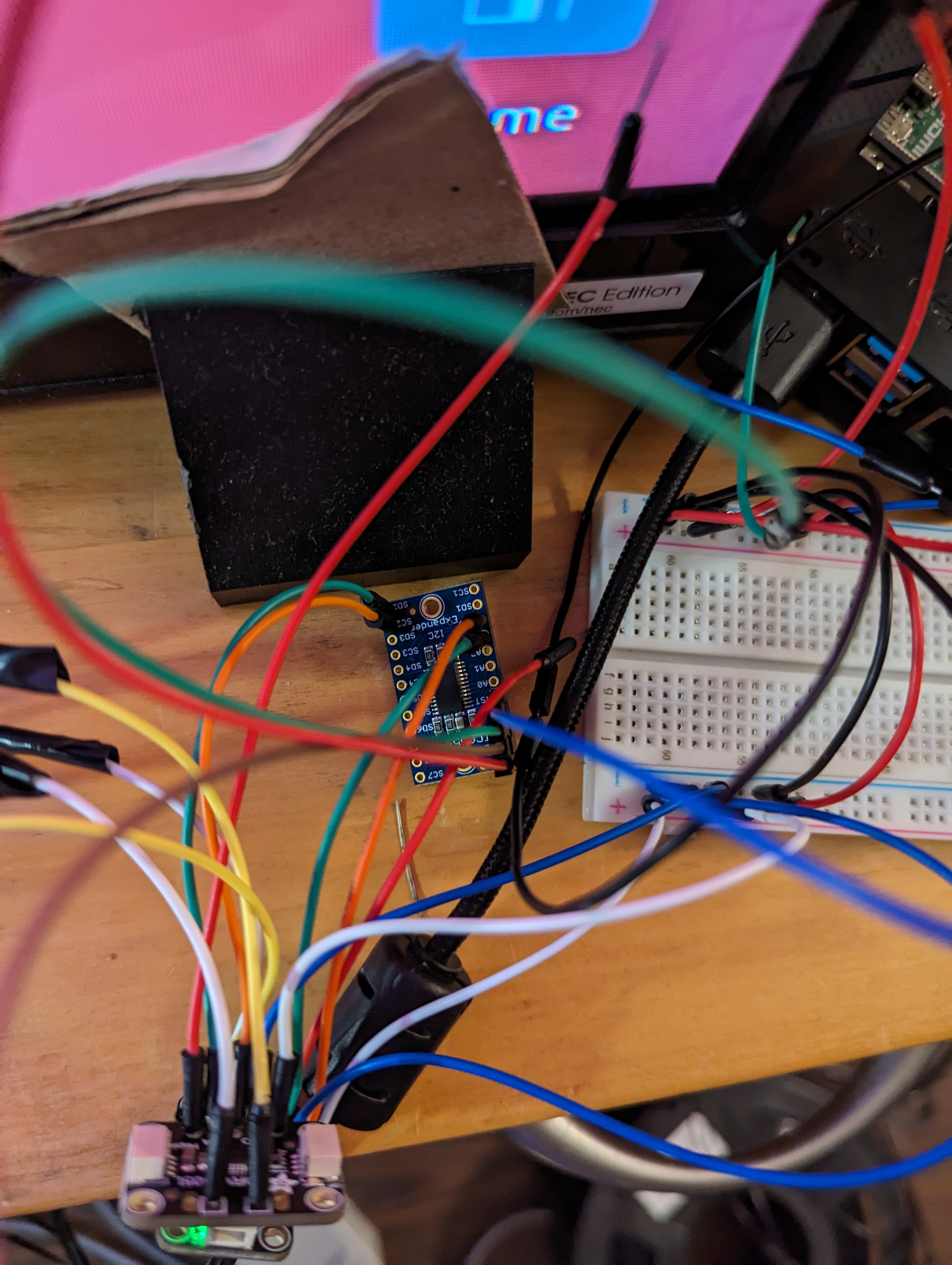
I2C Issues
We decided to reinvestigate the I2C bus to verify that the commands were actually being sent to both motor controller boards. Since the motor controller boards have the same I2C address, an I2C MUX had to be used to effectively select which board we want to communicate with. We noticed that when we ran an I2C scanner, only the right vibration motor controller, which was on channel 0 of the MUX was being detected. The left vibration motor controller was connected on channel 2 and wasn’t detected.
We decided to take a software approach first to exhaust all those options before modifying the hardware. This approach was unsuccessful so we tried some hardware techniques such as using pull-up resistors on the SCL and SDA lines of the the channels which was done to no avail. Finally, we decided to switch the channel which the left vibration motor controller was on to channel 3. The device was now finally being detected.
We then took a systematic approach to reach the final integration level of testing the vibration motor fully with the LiDAR detection to great success.
Resolution
It appears that the 2nd channel of the I2C MUX is malfunctioning. This cause is unknown, but we know that channel 3 is now fully and consistently working with the left vibration motor allowing us to continue development.